Tuesday, August 4, 2015

Transposing Angles: A Quick and Dirty Method

If we have a faceting diagram intended for one gemstone material, how do we transpose the angles for a different material? That is a pretty broad topic, so let's begin with diamonds. Why diamond? Because angles for diamonds have been studied documented extensively.

Let's start with a round brilliant in diamond. The angles below were taken from Michael Cowing's Central Ideal angles. Cowing discovered that there was an overlapping “sweet spot” in the recommended angle ranges in several different studies of angles for diamonds. Here is a combination of angles from near the center of the overlap.


Ideal Brilliant for Diamond
Angles for Diamond, R.I. = 2.42
57 + 64 girdles = 121 facets
8-fold, mirror-image symmetry
64 index
L/W = 1.000  T/W = 0.560
P/W = 0.443  C/W = 0.157
Vol./W³ = 0.206

CROWN
90.00° (64 total)
A 41.20° 02-06-10-14-18-22-26-30-
        34-38-42-46-50-54-58-62
B 34.00° 64-08-16-24-32-40-48-56
C 22.50° 04-12-20-28-36-44-52-60
 0.00° Table
PAVILION
1 42.20° 02-06-10-14-18-22-26-30-
        34-38-42-46-50-54-58-62
2 41.00° 64-08-16-24-32-40-48-56

This particular combination gives the so-called Hearts & Arrows pattern.
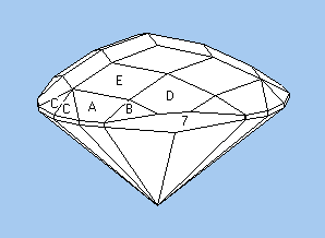
Diamond, RI=2.42, 34°crown mains
This image was produced with GemRay using a 15° head shadow. The arrows pattern (8 arrows pointing outward like spokes) is a reflection of the viewer. (The hearts are only visible from below under special lighting conditions.) Diamonds that show this pattern have exceptional symmetry and have angles that are known to perform well, so dealers can charge a premium for them.

How would we go about changing the angles to get the same appearance in CZ, refractive index of about 2.16? Let's start with the pavilion angles. How do we need to change the pavilion angles to get the same performance? The answer is: Not at all! Why is this so? A ray of light reflects totally off of a facet if its angle of incidence is higher than the critical angle. A light ray travelling vertically downward through a gemstone will reflect if the pavilion facet angle is above the critical angle, so provided that all of the light rays totally reflect off the pavilion facets, the same angles will work. This is because the paths of reflected rays do not depend on the refractive index. Now let's turn our attention to crown angles.

Since CZ has a lower refractive index than diamond (2.16 vs 2.42), it bends light less than diamond. How can we make it bend light more? By raising the crown angle. How much more? It turns out that if we scale the crown by the ratio of the refractive indices, the paths of light rays will be very similar. In GemCad, you can just use the Edit->Scale menu command with the +Z (crown) option with 2.42 in the Multiply by box and 2.16 in the Divide by box. In GemRay, you can type 2.42/2.16=1.120 in the Crown scale factor box. This raises the crown mains from 34 to 37.1°. (You would get the same results in GemCad if you clicked in a main facet and changed the number in the New Angle box from 34 to 37.1. The result is the left image below.

If you aren't using GemCad or GemRay, you can get the same result by taking the tangent of each angle, multiplying it by the ratio of the refractive indices and then taking the arc-tangent of the result.

Now what if we want to go the other way and make a moissanite look like a diamond? Moissanite has RI=2.62, which is higher than diamond, so to get the same general appearance, we need to lower the crown, scaling by the ratio 2.42/2.62=0.924, lowering the crown mains from 34 to 31.9°. Again, we leave the pavilion angles unchanged. The result is the right image below.
CZ, RI=2.16, 37.1° crown mains
Moissanite, RI=2.62, 31.9° crown mains
While not a perfect match, the reflection patterns are very similar.

This “quick and dirty” process breaks down somewhat for larger changes in RI. When we go down in refractive indes to quartz, RI=1.54, the approximation predicts a scale factor of 2.42/1.54=1.57 for a crown angle of 46.6°. The image below shows what you probably already knew: It's really hard to make quartz look like diamond.
Quartz, RI=1.54, 46.6° crown mains
Also, our pavilion angle of 41° is only 0.5° above the critical angle for quartz, so these angles not great choices for quartz. The dark perimeter represents light rays that make only one reflection off pavilion facets and leak out the other side.

It is worth noting that the central bullseye in all three simulations represents light rays that both enter the table make two bounces off pavilion facets and exit the table towards the viewer's eye. The size of this spot depends on the table size, the pavilion angle, the crown height and refractive index. Since these rays only hit the table and pavilion facets, the size of the spot is independent of crown angles (but the crown height does change as a function of crown angles). The variable with the largest effect on this spot size is the pavilion angle. Since we have kept the table size and our pavilion angle fixed, the size of this spot remains approximately fixed.

Here are some general rules for adapting a diagram for a different refractive index:
  • If the pavilion angles work well for one material, they will generally work unchanged for the other material unless the angles are near or below the critical angle. 
  • For small changes in refractive index, scaling the crown by the ratio of the refractive indices will usually get you in the right ballpark.
  • If increasing the refractive index, decrease the crown angle, and vice-versa.

For replicas of diamonds in CZ, if you know the angles for diamond, the above method will give you a replica with similar reflection pattern. (Some fine-tuning might get you even closer.)

For a much more thorough study of angles, read Bruce Harding's article Faceting Limits. The above method applies to angle changes that stay within the same zone between the same limits. Angle combinations in a different one of Harding's zones might be better for the other material. If adapting a design for quartz that has a low crown, and if you want to cut it in, say, CZ, it may be better to go against the rules above and raise the crown angle for higher refractive index. Also, you will want to make exceptions if cutting to deepen the color saturation of light stones or lighten the color of dark stones.

Thursday, October 2, 2014

From Retro Reflector to Simple Triangle

In the last post, we looked at the optics of a retroreflector corner-cube prism. In this post, I'll morph a retroreflector into a simple triangular gemstone.

Recall that a retroreflector's function is to reflect all of the light rays back towards their source parallel to the direction the ray entered. It does so even when tilted. This makes for a lousy gemstone because all of the light rays reflect back to their sources, and none make it to the viewer's eye. All the viewer sees is her reflection. Scintillation is almost nonexistent.

Let's make the following changes:
  1. Lower the pavilion angle from 54.74° to 49°
  2. Vertically split the 3 pavilion facets into 6
  3. Change our equilateral hexagonal outline to one with pointed corners
  4. Make a single-cut crown
Here is the diagram for the resulting gemstone:

Now let's look at the path of a typical light ray:


You'll notice that the ray makes three bounces off pavilion facets, similar to how it did with the retroreflector, but it is no longer reflected back parallel to its entry. Here is a tilt animation of the stone cut in quartz, R.I.=1.54 made with GemRay:
The stone is tilting 30° in each direction. Here is GemRay's tilt analysis:


The dashed curves consider just the portion of the stone visible under the table facet as the stone tilts. The stone tilts 13° in one direction and 20° in the other before the pavilion windows. Read GemRay's User's Guide for a discussion of the three lighting models. This is excellent tilt performance for a design for quartz. This design works well over the entire range of refractive index from fluorite (R.I.=1.43) to moissanite (R.I.=2.62) without changing angles. In fluorite, the design can be tilted is 8° before it windows. 

The scintillation OK considering the small number of facets—only 13, not counting the girdles. The obvious way to increase scintillation is to cut more facets.

In the future posts, I'll compare this design to some other simple designs and show how to best make use of the "three-bounce" pavilion.


Wednesday, September 24, 2014

The Retroreflector

A retroreflector corner cube prism is a special type of prism used in optics to reflect a light beam back to its source. Unlike a flat mirror, a retroreflector doesn't have to be oriented in any particular direction. The Apollo astronauts left retroreflectors on the Moon. Today, astronomers shoot laser beams and time how long it takes the light to go from the Earth to the Moon and back, about a 2.5 second round trip. With these measurements, they can measure the Moon's orbit precisely. Read more about it here.

Imagine a cube of glass with polished facets. Cut off one corner to get a 3-sided pyramid, polish the triangular cut face, and you have a retroreflector. The points of the triangle leak light, but the central portion reflects. Like a gemstone pavilion, the prism doesn't have to be silvered to reflect but relies on the principle of total internal reflection.

You can purchase a retroreflector from an optical supplier, even on ebay. If you want to facet your own, here are the instructions:


The 6 girdle facets don't have to be polished. Here are some paths of light rays hitting a retroreflector:


The table facet is tilted with respect to the rays, so each ray gets refracted slightly as it passes through the table. Each ray hits each of the 3 "pavilion" facets that make up the corner cube. After the third bounce, its path is exactly parallel to its path when it entred the stone but displaced laterally. When a light ray exits, it gets refracted again by the same amount as when it entered, so each light ray leaves the prism exactly parallel to the path it entered. This is true regardless of the refractive index.

Now the pavilion angle of 54.74° is quite steep for a gemstone pavilion. You might think that if three facets are good, six would be better. What you will find is that light makes one bounce off a pavilion facet and then leaks out the other side. This high angle just does't work with your average conical pavilion.

One of the problems in gemstone design is light leakage when a stone is tilted. This is especially true for materials of low refractive index. The retroreflector continues to do its job even when tilted. This true partly because the three bounces can "share the load" better than with two bounces. 

Now a retroreflector makes a lousy gemstone. The biggest problem is "head shadow" or viewer refection. All that you can see in the stone is your own reflection. Even if you tilt the stone, you still see your reflection. The light rays from lights get reflected back to their source instead of towards the viewer. The next problem is scintillation—three pavilion facets don't break up the light very much.

In the next post, we'll see how to borrow some of the good features of a retroreflector and use them to our advantage in gemstone design.

Most of this material was covered in an article by Paul W. Smith in Gerald Wykoff's American Gemcutter magazine, September, 1987 and in my article in the Newsletter of the Texas Faceters' Guild, Jan-Apr, 1996.


Tuesday, September 2, 2014

More Hearts from Triangles

After rediscovering the triangle-to-heart transformation I described in my last post, I decided to look for other candidates, and I found one that I like a lot. I created a design I called Cube Illusion Triangle because the facet pattern top view looks like a stack of cubes. It is on www.facetdiagrams.org as design 13.110. There is a link to download the GemCad file at the bottom of that page.

Below it the design after I morphed it into a heart. I managed to work in the extra facets to round out the corners in a way that continues the other lines. The step 1 facets on the above pavilion just didn't fit in with the heart, so I went with what Sid Word of Portland, OR called a "mono pavilion." Sid was the king of checkerboard designs. He discovered that with a design with no table and lots of small facets on the crown, a simple, conical pavilion often works just fine. I posted the Cube Illusion Heart as design 10.061.
Note that the flat, top part of the heart does not have a level girdle (facet 7). Here is a screenshot from GemCad:

Would you like to try this technique yourself? Download the GemCad file and try it yourself. Hungry for more? Here are a couple that I enjoyed playing with: 

  • London Shield 13.090 by Dennis Durham
  • Brittania (Britannia) 13.039 by Robert Long

Wednesday, August 27, 2014

From Triangle to Heart and Beyond

Hearts, pears, shields and the like can be some of the most challenging designs to cut—lots of steps. Nearly 21 years ago, I did a design called the Tri-Heart, design 10.037 found on www.facetdiagrams.org. To design this, I started with 3-fold, mirror-image symmetry on the pavilion. Recently a designer named Roland Arajs started with my Tri-Heart and played some more with the symmetry, creating his Vortex Tri-Heart. This inspired me to take another look at morphing other triangular designs into a hearts.

When designing and cutting a heart, there are two important advantages to starting with a triangular design. First, you can end up with a design that is easier to cut. With the usual 1-fold, mirror-image symmetry of a heart, you only get to cut one or two facets at the same angle and mast (or platform) height. This means lots of steps with a lot of time spent changing the settings on your machine and more chances for mistakes. With 3-fold, mirror-image symmetry, you can cut up to six facets at the same angle and mast height. With a suitable design (and careful dopping), the cutting sequence can be much simpler.

The second advantage is with optical performance. When light rays hit a pavilion that is a three-sided pyramid in shape with steeper angles than usual, interesting things happen. Many light rays bounce three times off pavilion facets instead of the usual two and then return to exit the crown. The result is better scintillation and better performance when the stone is tilted. This can be particularly beneficial for materials of lower refractive index—quartz, R.I=1.54, or even lower, glass, opal, fluorite, etc.

I started out with Trilliant C 13.067 by Basil Watermeyer, calculated by Norm Steele. The symmetry wasn't quite complete in the design in the database, so I tweaked it. I made the corners less sharp, moved some meets around. I optimized the angles for quartz, (but they also work well unchanged for CZ). Note the steep angles on the pavilion. This is to take advantage of the three-bounce principle. I duplicated angles wherever possible. I also made sure the steps 1 and 2 facets on the pavilion meet at a temporary center point, so it's easy to make the outline. I posted the design on www.facetdiagrams.org as design 13.067D. Here is a screenshot:
The next step on our path to a heart shape is to round off all three corners. Now we really only need to round off two corners for our heart, but if we round off all three, we can take advantage of GemCad's 3-fold symmetry to get six facets for the price of one. (We only need 4 four the price of one, but we'll return the extra two later). Below is the result. I call this version the Bulgy Trilliant. I posted this on www.facetdiagrams.org as design 13.175.
We are nearly there. To get a heart shape, we need only delete the "rounding" facets on the bottom corner and cut a flat on the top. Here is my Trilliant Heart. I posted it as design 10.060.

Note that the girdle line is not level on the flat side. You can carve a notch in the flat side if you have the equipment and know-how. There are just 15 steps, including the girdle and table!

Finally, what if we just round off one corner of our Trilliant? The result is my Trilliant Shield, which I posted as 23.063.

This is a re-cut option for a triangle with a chipped corner. You might notice that I kept the step names for all four designs. The heart is the only one with step 5.


Monday, August 25, 2014

Adapting the Cushport On the Fly for L/W=1.25

This post builds on the previous one, so please read that post first. The length-to-width given in the header of the diagram is L/W=1.356, but let's say we want to cut it for L/W=10 mm by 8 mm=1.25 instead.

How to get started? When cutting on your faceting machine, you could start by cutting the stone to width. Cut the two step 1 facets at 90° at index settings 96 and 48. Alternate until the width is about 8.5 or 9 mm (to allow for progressing to finer laps). Then cut the four step 2 facets at 90° at 20-28-68-76. Alternate until length is 10.5 or 11 mm again allowing you to "sneak up" on the final 10 mm width when you pre-polish.

How to proof-cut the outline in GemCad? The trick is to type in some coordinate points in GemCad's Points field in the 90° New Facet Info box. First a review of GemCad's coordinate system. GemCad's x axis increases to the right, and the y axis coordinate increases down in GemCad's top view. The z coordinate increases up out of the screen. GemCad's coordinate system is in arbitrary units, not millimeters. A cube of two units on a side is about as big as will fit on the screen. Our 8 by 10 stone needs to extend from -1 to 1 on the axis and from -0.8 to 0.8 on the axis.

Set the Symmetry to 2-fold, mirror-image. Next, enter the point (0, 0.8, 0) on any of the 3 lines of the Points field of the New Facet Info box by typing "0 0.8 0" without the quotes. Whenever the mouse focus changes, GemCad will reformat it, adding in decimal point and some zeroes. Then enter an Angle of 90° and an Index of 96. Click the Apply/Cut button, and GemCad will cut the pair of girdle facets at 96-48.

Next, enter the point (1,0,0) by typing "1 0 0" without the quotes on any of the 3 lines in the Points field. Then enter an Angle of 90° and an Index of 20. GemCad will cut four more girdle facets, and our girdle outline should be a long hexagon. You should see L/W=1.250 at the bottom status line. You might have noticed that the coordinates were zero. Why zero? Well, the z coordinate is arbitrary since girdle facets are parallel to the line of sight in the top view, so our z coordinates could have been anything, and 0 is easy to type.

OK. Now we need to cut our last set of four girdle facets. On the faceting machine, cut facets at 90°at 04-44-52-92. How deep? Cut until the outline shape looks pleasing and until you cut away any flaws and you get 4 good corners.

In GemCad, you can just set a point by eye to cutting depth. Another way is to enter the Center-to-Facet Distance. This is the distance from the center of the stone, the point (0, 0, 0) to the plane of the facet. When your protractor is set at 90°, this is the distance from the axis of the dop to the plane of the lap. On some faceting machines, you can read off this distance with a scale. I found that for this L/W, a center-to-facet distance of 0.85 gave a pleasing outline, to my eye. Type in 0.85 in the Center-to-Facet Distance box. Enter an Angle of 90°and an Index of 4, and GemCad will cut the last 4 girdle facets.

On the faceting machine, for our 8 by 10 mm stone, another way to reproduce this shape is to cut until the opposing facets are 8.5 mm apart (rough cut to 9 or 9.5 mm apart) with the calipers flat to the opposing facets.

Here is our girdle outline:


Now let's cut the rest of the pavilion using our diagram at the end of the last program--the one with the wrong L/W.


Not too bad, considering. Now we have some decisions to make. If I were cutting a valuable piece of rough, I probably wouldn't worry too much about the bad meets at 3 and 5. After all, in a commercial appraisal, good meets don't add to the value of the stone. If the poor meets bother you, you can make them meet by using your cheater when pre-polishing or even polishing. In GemCad, you can fix them by giving GemCad 3 points and letting it figure out the index and angle. Note that we could get facet labeled Y to meet by lowering its angle and leaving its index alone. However, if you click on points 4 and 6, put your cursor inside facet Y, click and select Uncut/Recut, you will find that the angle needed is below the critical angle for quartz. It would be fine for corundum, though. If you click on points 4, 5 and 6, selecting Use to Cut each time, then click in Y and click Uncut/Recut, and click the Apply/Cut button, GemCad will change mostly the index instead of angle. Similarly you can do the same thing for points 1, 2, and 3 and facet X. Here is the result:


Facet X ended up at 56.5 at index 6.7. Facet Y ended up 42.2 at index 21.2.

at With GemCad, you can label the opposite girdle facets with the same number, and GemCad will show that flat-to-flat dimension in the table of dimensions. Here, I labeled both of them 3, and it shows (3 3)/W=1.062 in the table of dimensions. For our stone, with W=8 mm, this dimension is 1.0625 x 8 = 8.50 mm. This corresponds to our 0.85 center-to-facet distance that we typed in.

Now we can transfer and cut the crown. When we use the angles and indices for the wrong L/W, we get the following:


Facet Z can be re-cut, cheating to meet points 1, 2, and 3. Here is the result:

While not the prettiest arrangements of facets, everything meets up, and the resulting stone will be pleasing. For reference, facet Z ended up at 27.6° at index 18.6.

Another possibility for this design is the idea of cutting to constant mast height instead of constant angle. Notice that this design has several sets of facets cut to the same angle but at different mast heights. Since this is a generic design, we could equally well cut adjacent steps using the same mast height but slightly different angles without changing the general look of the design. Depending on which adjustment is easier, it might make sense to leave the mast height alone and adjust the angle instead.

So, what have we learned? Meetpoint faceting is not always the best approach--adapting on the fly to the shape of the rough, eliminating flaws as you go is a valuable skill. By proof-cutting with GemCad, you can work out ideas for how to adapt on the fly. With this design, you can save all of the adjustments to the very end by cheating in one or two key sets of facets. If you want to make this design fully meetpoint for your L/W of choice, GemCad gives you the tools to do this. Diagonal measurements can be a useful preforming technique.

Tuesday, August 19, 2014

Cutting the Cushport—Design L/W

Here is my Cushport design from my previous post for L/W=1.356, as downloaded from www.facetdiagrams.org.
Note the diagonal dimension:
 (2 2)/W=1.058
To get GemCad to display this diagonal dimension in the table of dimensions, label opposing facets on the girdle with the same name. See in the bottom view where there are two facets labeled 2? Anytime GemCad sees two parallel girdle facets at the same mast height labeled the same, it will add this diagonal dimension to the table of dimensions. It is important to note that this is not the distance from the tips of the arrows but is the distance you would measure if you put the jaws of your caliper flat against both the indicated facets. It's the distance between the planes of the two facets.

So how to we use these diagonal dimensions? Let's say, for the sake of discussion that we are cutting a piece of rough and we think we can get a stone of length 13 mm. The width for this pattern would be 13/1.356=9.59 mm. First off, make sure that the rough is at least this size. When cutting, we could cut step 1 facets alternately until we get to 9.59 mm (allowing an additional half to one mm to grind away when prepolishing). Then cut step 3 facets until we get our length 13 mm (plus some extra). Then cut step 2 facets alternately. But how deep? The diagonal dimension gives us a clue. Cut them alternately until the diagonal dimension measures 1.058*W=1.058*13/1.356=10.14 mm. Again, this dimension is not the distance between the tips of the arrows but is instead be measured with the jaws of the caliper measured flat to the girdle facets.

How to proof-cut the outline in GemCad? The trick is to type in some coordinate points in GemCad's Points field in the 90° New Facet Info box. First a review of GemCad's coordinate system. GemCad's x axis increases to the right, and the y axis coordinate increases down in GemCad's top view. The z coordinate increases up out of the screen. GemCad's coordinate system is in arbitrary units, not millimeters. A cube of two units on a side is about as big as will fit on the screen. Our stone needs to extend from -1 to 1 on the axis and from -W/L to W/L on the axis. For our example, W/L=1/1.356=0.7375.

Set the Symmetry to 2-fold, mirror-image. Next, enter the point (0, 0.7375, 0) on any of the 3 lines of the Points field of the New Facet Info box by typing "0 0.7375 0" without the quotes. Whenever the mouse focus changes, GemCad will reformat it, adding in decimal point and some zeroes. Then enter an Angle of 90° and an Index of 96. Click the Apply/Cut button, and GemCad will cut the pair of girdle facets at 96-48. 

Next, enter the point (1,0,0) by typing "1 0 0" without the quotes on any of the 3 lines in the Points field. Then enter an Angle of 90° and an Index of 20. GemCad will cut four more girdle facets, and our girdle outline should be a long hexagon. You should see L/W=1.356 at the bottom status line. You might have noticed that the coordinates were zero. Why zero? Well, the z coordinate is arbitrary since girdle facets are parallel to the line of sight in the top view, so our z coordinates could have been anything, and 0 is easy to type.

To get the other girdle facets, we have to make use of the diagonal dimension. We will use the concept of Center-to-Facet Distance. This is the distance from the center of the stone, the point (0, 0, 0) to the plane of the facet. When your protractor is set at 90°, this is the distance from the axis of the dop to the plane of the lap. On some faceting machines, you can read off this distance on a calibrated ruler. In GemCad, we'll have to do a bit of math. Recall that our stone's length, the x coordinate goes from -1 to 1, so L=2 GemCad units. Our width W is 2 divided by L/W. W=2/1.356. Our diagonal dimension is 1.058W = 1.058*2/1.356. The center-to-facet distance is exactly half this distance, so it is 1.058/1.356=0.7802.

Enter 0.7802 in the Center-to-Facet Distance box, an Angle of 90° and an Index of 4, and GemCad will  finish the girdle outline. From here on, the design is pure meetpoint.

In my next post, we'll look at how to adapt this design for other L/W, even adapting it "on the fly."